

IRIG Time Code Formats
Contents:
MEINBERG IRIG Receivers and IRIG Generators
Overview
The term IRIG signals is frequently used to refer to a whole group of serial timecodes, which use a continuous stream of binary data to transmit information on date and time. The individual time code formats can be distinguished by the signal characteristics, e.g. modulated versus unmodulated, which require different ways of signal transmission, by the data rate, and by the kind of information included in the transmitted data.
Over the years different organizations have published several standards defining the basic timecodes and also extensions to those time codes to meet the requirements of new applications.
Back in 1956 the TeleCommunication Working Group (TCWG) of the American Inter Range Instrumentation Group (IRIG) was mandated to standardize different time code formats, resulting in IRIG Document 104-60 which was published in 1960. In 1970 the document was revised to IRIG Document 104-70, and later published as IRIG Standard 200-70. In 1995 there was another revision which became IRIG Standard 200-95. The latest revisions are IRIG Standard 200-98 from 1998 which defined a group of Manchester modulated signals, and IRIG Standard 200-04 which is the current version specifying some new codes which also transmit a year number.
A copy of the latest version can be obtained by writing to:
White Sands Missile Range
New Mexico, 88002-5110

Description of IRIG Formats
The name of an IRIG code format consists of a single letter plus 3 subsequent digits. Each letter or digit reflects an attribute of the corresponding IRIG code. The following table contains standard code formats defined in IRIG standard 200-98:
| IRIG A | IRIG B | IRIG D | IRIG E | IRIG G | IRIG H |
|---|---|---|---|---|---|
| A000 | B000 | D001 | E001 | G001 | H001 |
| A003 | B003 | D002 | E002 | G002 | H002 |
| A130 | B120 | D111 | E111 | G006 | H111 |
| A132 | B122 | D112 | E112 | G141 | H112 |
| A133 | B123 | D121 | E121 | G142 | H121 |
| D122 | E122 | G146 | H122 |
The code format names are composed as described below:
| First letter: Rate Designation |
A B D E G H |
1000 PPS 100 PPS 1 PPM 10 PPS 10000 PPS 1 PPS |
| 1st Digit: Form Designation |
0 1 |
DC Level Shift (DCLS), width coded, no carrier Sine wave carrier, amplitude modulated |
| 2nd Digit: Carrier Resolution |
0 1 2 3 4 |
No carrier(DCLS) 100 Hz / 10 millisecond resolution 1 kHz / 1 millisecond resolution 10 kHz / 100 microsecond resolution 100 kHz / 10 microsecond resolution |
| 3rd Digit: Coded Expressions |
0 1 2 3 6 7 |
BCD, CF, SBS BCD, CF BCD BCD, SBS BCD, BCD_Year BCD, BCD_Year, SBS |
Abbreviations used in the table above:
- BCD - Binary Coded Decimal, coding of time (HH,MM,SS,DDD)
- SBS - Straight Binary Second of day (0....86400)
- CF - Control Functions depending on the user application
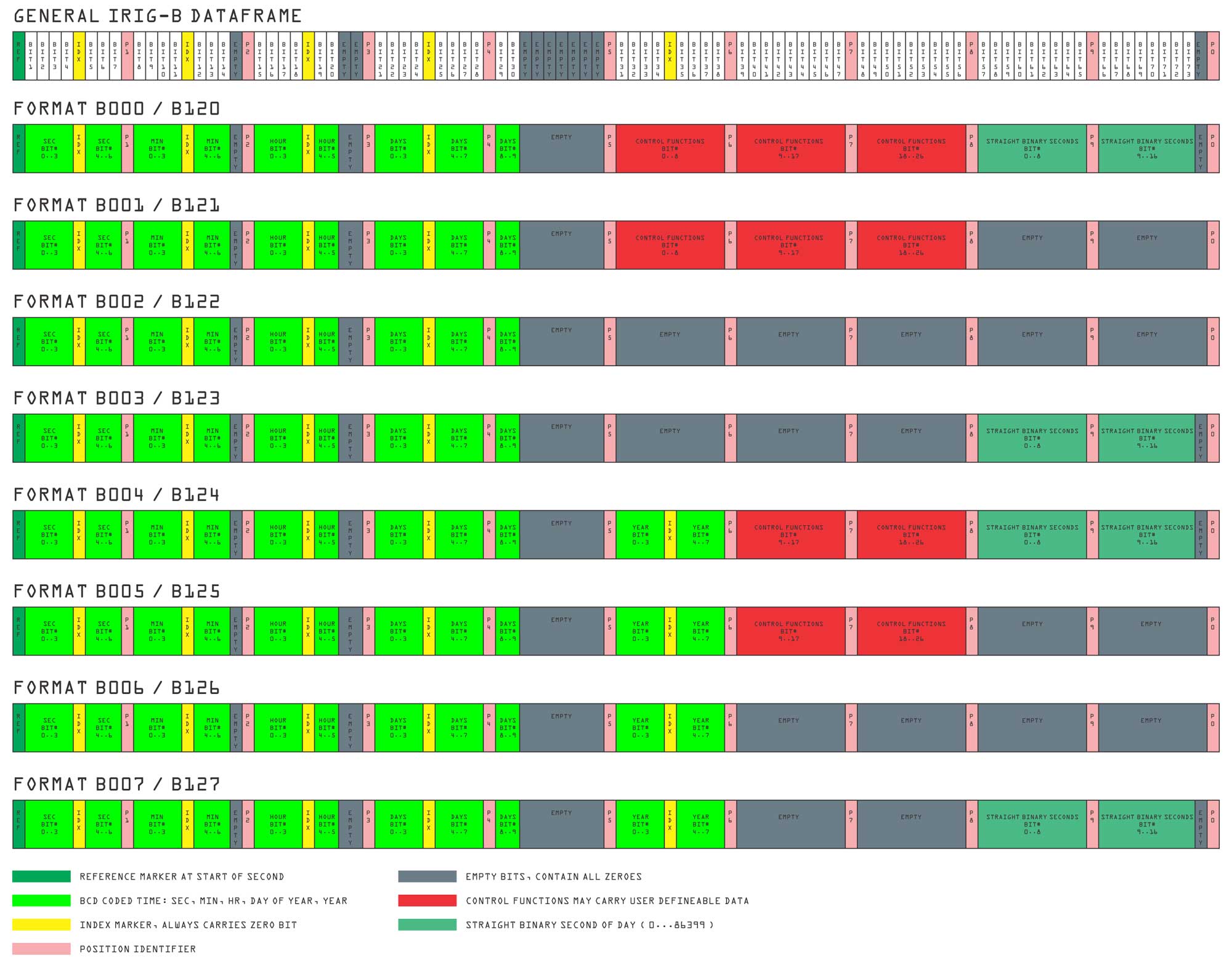
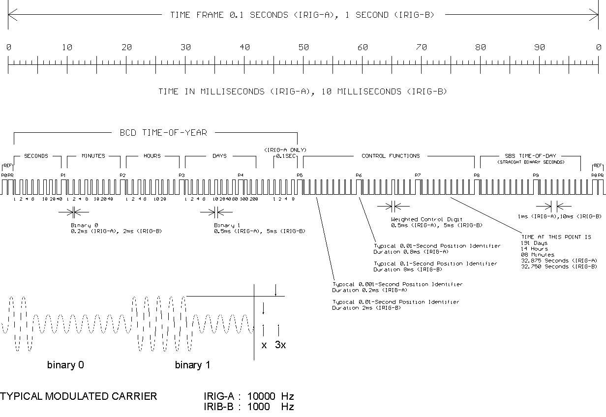
This drawing shows the dataframes from IRIG-B Code (IRIG - B000/B120 to IRIG - B007/B127)
![]() You can download this overview as an PDF here.
You can download this overview as an PDF here.
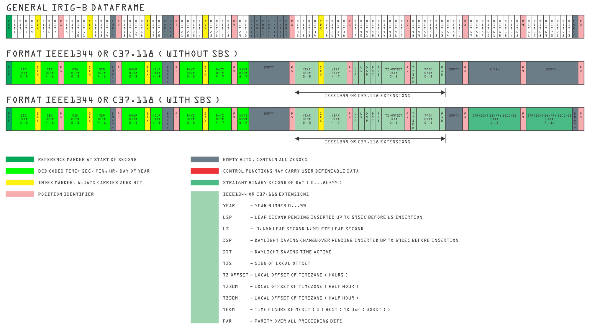
This drawing shows the dataframes of IEEE1344 / C37.118 code
![]() You can download this IEEE1344 overview as an PDF here.
You can download this IEEE1344 overview as an PDF here.
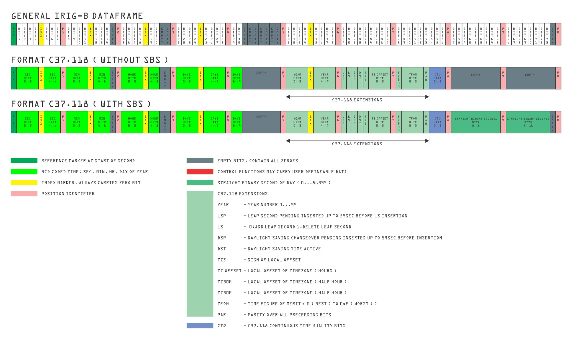
This drawing shows the C37.118 dataframes
![]() You can download the C37.118 overview as PDF file here.
You can download the C37.118 overview as PDF file here.
The graphic below shows the general structure of IRIG codes:
Modulated IRIG Codes
Modulated IRIG codes consist of a carrier frequency which is modulated with the time code. The carrier frequency is determined by name of the time code format as mentioned in the table above.
Example: B123
- The second digit indicates carrier frequency (2 -> 1kHz)
- The carrier envelope corresponds to the unmodulated code
- The mark-to-space ratio is typically 10:3 (can be in a range of 10:3 up to 10:6)
An also commonly used format is AFNOR NF S87-500, a French standard, not an IRIG code, but very similar
Techniques for transmission of modulated codes:
- coaxial cable terminated in 50Ω or high-Z, 600Ω e.g. (a standard method)
- symmetrical twisted pair
- analog fiber optic transmitter/receiver (rare)
The signal level for IRIG code has not been defined in IRIG 200-98.
Unmodulated IRIG Codes
- standardized in IRIG 200-98
- DC Level Shift Codes without carrier
Techniques for transmission of unmodulated codes
- TTL Level over coaxial cable (should be terminated correctly)
- RS422 differential Level, twisted pair lines
- RS232 Level, shielded cable (only short distances)
- Fiber Optic
Meinberg IRIG Receivers
IRIG Time Code Receiver (Eurocard)
- Two independently configurable serial ports
- Pulse per second (PPS) output at TTL Level
- Pulse per minute (PPM) output at TTL Level
- Emulation of DCF77 time code
PCIe Time Code Receiver
- PCIe card, PCI Express r1.0a compatible
- Two independant serial RS-232 interfaces
- Can generate interrupts
PCI Express Time Code Receiver and Generator
- Single lane (x1) PCI Express (PCIe) Interface
- Two serial ports
- Integrated Solution including a Time Code Reader and a Generator
- Can generate interrupts
- Programmable Pulse Outputs
- DDS frequency synthesizer
- Optional optical inputs/outputs available
Network Time Server LANTIME M300
- IRIG disciplined NTP Time Server
Meinberg IRIG Generators and combined Readers/Generators
IRIG TimeCode Generator
- Can be synchronized by Meinberg GPS or PZF clocks
- Can be equipped with oscillator for special purposes
- Configurable serial port
- Selectable timestring for synchronization (Meinberg Standard / Uni Erlangen)
- ALC (Automatic Level Control) for AFNOR NF S87-500 compatibility
- PPS regeneration for special purposes
- Bootstrap loader/flash Memory allows SW update via serial port
PCI Express Time Code Receiver and Generator
- PCI Express Interface
- One serial port
- Integrated Solution including a Time Code Reader and a Time Code Generator
- Can generate interrupts
- Optional optical inputs/outputs available
PCI Express GPS Receiver and IRIG Time Code Generator
- PCI Express Interface
- One serial port
- Integrated Solution including a GPS receiver and a Time Code Generator
- Can generate interrupts
GPS receiver with LC Display
- GPS receiver with IRIG time code generator
- Up to 4 RS232 interfaces
- Standard frequency outputs
- Pulses per second and per minute
- 2 time trigger inputs
- DDS frequency synthesizer
- DCF77 simulation
- Antenna connected with up to 300 m of standard coaxial cable RG58
The GPS receiver can be ordered with the Time Code option or - in a modular system - is capable of providing time synchronization for a Time Code Generator (TCG - see above).
