Time Synchronization in Telecom Networks
Precise Time Synchronization for Telecom Networks.
- What is time synchronization and how does it work?
- Which solutions exist for telecom networks and attached networks?
- Which accuracy and stability is required?
- Why should manufacturers and operators of equipment for telecom networks care about these terms?
This document has been created to answer these questions and offers you
a comprehensive and easy-to-understand introduction. Read on ...
Many Thanks to Mr. Gerd Backhaus for his friendly support at this publication!
Telecom Time Synchronization Overview
Network synchronisation is an important task to get excellent performance and quality of service for the subscribers.
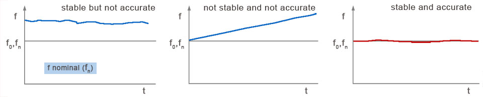
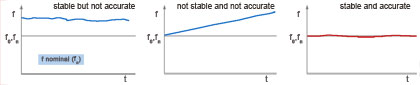
Diagram of Clock Stability and Accuracy
 click on the picture to zoom the diagram!
Communication requires excellent quality of service in the network!
Synchronization equipment, planning and installation account for 1% of the overall project equipment costs.
Synchronization must be considered and planned from the very beginning of a project.
If the manufacturer cannot deliver synchronization equipment, he must inform the customer so that the customer can take steps to:
- Identify appropriate synchronization equipment
- Plan system synchronization appropriately
- Seek a Time & Frequency Specialist if necessary
Otherwise the performance in the network will suffer and will not comply with the ITU (International Telecommunication Union) standard.
After an inventory of the hardware available, a preliminary network overview is made including the available timing reference sources.
This can be used to plan the synchronization of switching devices.
For transmission network synchronization (SDH), a plan must be developed with a special sync planning tool.
In ITU-Recommendation G.811 (Timing Characteristics of Primary Reference Clocks) a network clock stability of 1 x 10 E-11
for the Primary Reference Clock (RPC) is recommended.
This accuracy is derived from 1 acceptable
slip in a 2 MBit/s transmission in an observation time of 70 days.
1 (frame) = 125 us
125 us / 70 d x 24 h/d x 3600 s/h = 2 x 10 E
-11 or +-1 x 10 E
-11
This clock stability can be generated by atomic clocks only!
There are different possible approaches to achieve the required accuracy.
Different solutions are possible and can be realized using
MEINBERG timing equipment.
PCM30 Frame (2 MBit/s)
125µs
Signalling Information or digital signal
Coded speech signal or digital signals in slot 1 - 15
Coded speech signals or digital signals in slot 17 - 31
Time slots
16
8 bit
Bit
1
Bit
8
(FAS)
Frame Alignment Signal
in Frames 1, 3, 5,...
(NFAS)
Non Frame Alignment Signal
in Frames 2, 4, 6,...
X 0 0 1 1 0 1 1
X 1 D N Y Y Y Y
488 ns
D: Service bit for critical alarm
(Alarm D=1)
N: Service bit for major alarm
(Alarm N=0)
X: Reserved bits for international use
Y: Reserved bits for national use

Synchronization with MEINBERG Equipment
Meinberg NTP Time Servers deliver a highly precise and stable clock for the system, and provide precise
NTP time for the network.
For example, reliable time stamps are necessary for diagnosis of system error messages.
Synchronization in Telecom - Networks with MEINBERG NTP Server
LANTIME GPS - NTP Server
LANTIME Network Time Server:
An NTP Server but also a clock source (2,048 MHz)
for Telecom - Networks
Outputs: (each)
4 x 2,048 MHz (G.703-13)
2 x 2,048 MBit/s (G.703-9)
10 m
100 or 200 m
10 m
Examples of Use
Synchronisation Hierarchy with
PDH transmission
ITU-Rec. G.811 df/F = 10 E-11
Transit
Node
Transit
Node
ITU-Rec. G.812 Type 1
Holdover Mode: 2 x 10 E-10/day
Local
Node
Local
Node
Local
Node
ITU-Rec. G.812 Type 1
Holdover Mode:
2 x 10 E-10/day
Holdover Mode:
2 x 10 E - 6/day
In synchronised mode 1 slip is accepted in 70 days!
2,048 MHz
2,048 MBit/s
2,048 MBit/s
2,048 MBit/s
2,048 MBit/s
2,048 MBit/s
2,048 MBit/s
Synchronisation Hierarchy with GPS receivers for SDH transmission
GALILEO GPS
GPS170/LIU
GPS170/LIU
GPS170/LIU
SDH Core A
SDH Core B
Exch.
SDH
SDH
SDH
SDH
SDH
SDH
SDH
SDH
MSC
MSC
MSC
M.E.*
M.E.*
M.E.*
M.E.*
* Mobile Equipment
How telecom switches are clocked
GALILEO/GPS
GPS170 / LIU
GPS170 / LIU
2,048 MHz
Synchronisation of second exchange
Exchange/Switch
The continuous PCM HDB3 coded data stream is received by using recovered clock from data stream
Clock
CP
E1
PCM 30
SN
PCM 30
PCM 30
2,048 MBit/s
E1
Recovered Clock
Clock
CP
T3
PCM 30
SN
PCM 30
PCM 30
T3
How a telecom switch is clocked
Galileo / GPS
Clock Stability:
10 E-11 !
Exchange/Switch
GPS170 / LIU
GPS170 / LIU
Clock synchronises SN and all other clock generators of switching peripherals
2,048 MHz
2,048 MBit/s
2,048 MBit/s
E1
E1
Clock Stability:
10 E-11 !
Clock Stability:
10 E-11 !
Clock Stability:
10 E-11 !
Clock
CP
PCM 30
PCM 30
SN
PCM 30
E1
2,048 MBit/s
The PCM transmitters are transporting speech, data and exchange clock stability in HDB3* coded data stream.
*HDB3 (High Density Bipolar of order 3 code) is a telecommunications line code
and is based on AMI.
Time Synchronization Terms and Glossary
|
BSC
Base Station Control: A GSM network element that handles BTS management and radio resource control.
The BSC manages the radio interface, mainly through the allocation, release, handover and power
control of radio channels. The BSC is synchronized over the PCM30-transmission of the
Mobile Switching Center (MSC) and send the received clock accuracy over further PCM30-transmissions
to the base stations.
BTS
Base Transceiver Station: A GSM network element that provides radio interface of the network.
The BTS controls the radio transmission to and from the mobile terminals. It is synchronized over
the PCM30 transmission from BSC and provides thereby the clock accuracy at the air interface.
GSM
Global System for Mobile Communications: GSM is the standard for the digital transmission technique
which is world wide adopted. GSM uses 900 MHz and 1.800 MHz for transmission and receiving.
MSC
Mobile Switching Center: A GSM network element, for exchanging mobile subscribers. The MSC arranges also
the switching to the subscribers in PSTN (Public switched telephone network).
The MSC is a digital switching center which contains components like TRAU, BSCs and BTSs for the radio interface.
The MSC is synchronized by local clock sources, e. g. PRCs, GPS receivers or clock outputs (T4) of SDH network elements.
PBX
Private Branch Exchange: A telephone switch located on a customer's premises that primarily establishes voice-grade
circuits over E1 links to PSTN (Public Switched Telephone Network).
PDH
The Plesiochronous Digital Hierarchy is a digital communication technology. PDH is based on the fundamental concepts
of Time Division Multiplexing (TDM).
Plesiochronous: (Greek - plesio, meaning near and chronos, meaning time)
The meaning of Plesiochronous therefore is "nearly synchronous".
Plesiochronous Digital Hierarchy is used to multiplex PCM30 transmissions to data streams with higher data
rates and for transmission over digital transport equipment such as fiber optic and microwave radio systems.
Although this transmission clock accuracy is not highly exact, the PCM30 data flow is transferred from synchronized
switching centers, regarding data and clock transparency.
Digital switching centers transfers synchronous PCM30 - data flow with this transmission technique to other
switching centers, and the recovered clock can be used for its own synchronization.
Much of the transport infrastructure based on plesiochronous digital hierarchy (PDH) is being replaced with
SONET or SDH based infrastructure.
PRC
Primary Reference Clock: Usually a caesium standard that provides frequencies compliant
with ITU G.811 or ETSI EN 300 462-6-1.
The accuracy of PRC must be > 1 x 10-11.
SLIP
Slip = PCM30 - Frame Slip - always arises in a PCM receiver. The data are stored error-free in a buffer,
which can take up 2 PCM Frames. The buffer is read with the clock of the switching center.
If the receiving switching center has a lower frequency than the transmitting switching center, the buffer
cannot read the data in the same rate as these is written by the transmitter. A buffer overflow occurs with
the result of a frame slip.
If the receiving switching center has a higher frequency than the transmitting switching center, the buffer
is faster read out, than it is filled. A buffer underflow occurs followed by a slip frame.
The slip rate is proportional to the frequency deviation between transmitter and receiver.
T3
Name of a clock input for clock generators (usually PLL) of a network element like e.g. switching center, BSC, BTS and SDH.
These inputs can be synchronized with 2,048 MHz or 2,048 MBit/s. The interfaces are either symmetrical or asymmetrical.
T4
Designation of the clock output of a clock generator in a network element e.g. switching center, BSC, BTS and SDH.
These output can deliver 2,048 MHz or 2,048 MBit/s. The interfaces are either symmetrical or asymmetrical.
E1
E1 transfers 32 time slots for each PCM frame - the first time slot of the first frame is the frame alignment signal (FAS).
This signal makes the recognition of the frame in the PCM receiver, so that thereafter the time slots with speech data
or data can be assigned to their goals correctly.
The first time slot of the second PCM frame is the non frame alignment signal (NFAS) to transfer alarms and checksums (CRC4).
Trau
Transcoder Rate Adaption Unit.
The TRAU belonged functionally to the mobile switching center. It has the GSM specific language coding and -
decoding (from 64 kBit/s to 16 kBit/s per voice channel in both direcctions).
It is synchronized over the PCM30-Transmission from MSC and transmits the received clock accuracy over
PCM30 transmissions to the base station control (BSC).
The TRAU is located at the BSC or directly at the MSC (mobile Switching center).
Sonet/SDH Definitions and Documentations
SDH (Synchronous digitally Hierarchy) is a standard technology for synchronous data communication on
optical media (in the USA usually known as SONET).
This technology is characterised by higher data rates and makes the transmission of the existing data
formats from the earlier PDH technology possible. Contrary to the PDH technology SDH network elements are synchronized.
The payload data is stored in "containers" with additional information - the "Overhead" and the "Payload" is transmitted as synchronous
transport module (e.g. STM-1). This transmission is normally accomplished over optical media.
STM-1 designates a data rate of 155 MBit/s - e.g. 63 PCM30 transmissions can be transported. These 155 MBit/s data stream
transports also the clock accuracy to the next SDH network element and synchronizes its clock generator. Thus a continuous
synchronization of the SDH network is possible.
The clock outputs (T4) of the SDH network elements can be used for the synchronization of further SDH network
components or other connected mobile equipment.
SDH uses the following Synchronous Transport Modules (STM) and rates:
STM-1 (155 MBit/s)
STM-4 (622 MBit/s)
STM-16 (2.5 Gbit/s)
STM-64 (10 Gbit/s)
|
SONET / SDH Technical Specs
SONET and SDH are related standards for synchronous
data transmission via fiber optic networks. SONET is an acronym for
Synchronous Optical NETwork, SDH is short for
Synchronous Digital Hierarchy. SONET is the US version of the American National Standards Institutue
(ANSI) standard.
SDH is the international version of the International Telecommunications
Union (ITU) standard.
SONET / SDH Digital Hierarchy
This table shows the SONET/SDH data rate hierarchy:
| Optical Level |
Electrical Level |
Line Rate (Mbps) |
Payload Rate (Mbps) |
Overhead Rate (Mbps) |
SDH Equivalent |
| OC-1 |
STS-1 |
51.840 |
50.112 |
1.728 |
- |
| OC-3 |
STS-3 |
155.520 |
150.336 |
5.184 |
STM-1 |
| OC-12 |
STS-12 |
622.080 |
601.344 |
20.736 |
STM-4 |
| OC-48 |
STS-48 |
2488.320 |
2405.376 |
82.944 |
STM-16 |
| OC-192 |
STS-192 |
9953.280 |
9621.504 |
331.776 |
STM-64 |
| OC-768 |
STS-768 |
39813.120 |
38486.016 |
1327.104 |
STM-256 |
The "line rate" describes the raw bit rate transferred via the optical fiber.
A certain amount of the bit rate are the overhead, that includes information that provides OAM&P: Operations,
Administration, Maintenance, and Provisioning information like framing, trace, multiplexing, status, and performance monitoring.
The payload rate which is the available bandwidth for user data as packets or ATM cells is calculated by the line rate minus the overhead rate.
Other rates like OC-9, OC-18, OC-24, OC-36, OC-96 were never widely implemented. Maybe higher rates like OC-3072 will defined in future times.
The SONET/SDH level designations including a "c" suffix (e.g. "OC-48c") indicate a "concatenated" or "clear" channel.
This shows, that the entire payload rate is available as a single channel of communications.
In these channels the entire payload rate can be used by a single flow of packets.
Opposed to the concatenated or clear channel is the "channelized".
In a channelized link the payload rate is divided into several fixed rate channels.
E.g. the payload of an OC-48 link can be subdivided into four OC-12 channels.
In this scenario the data rate of a single cell or packet flow has its limitations in the bandwidth of the individual channel.
ANSI SONET Standards
The ANSI coordinates and approves the SONET standards.
These standards are developed by the T1 Committee that is
sponsored by the Alliance for
Telecommunications Industry Solutions (ATIS) and accredited by ANSI to develop network and interoperability standards for the US.
T1X1, dealing with "digital hierarchy and synchronization" and
T1M1, dealing with "internetworking operations, administration, maintenance,
and provisioning" are the primary T1 Subcommittees developing SONET.
Below are some important standards from ANSI. For a complete set of SONET standards please visit the
ANSI homepage.
- ANSI T1.105: SONET - Basic Description including Multiplex Structure, Rates and Formats
- ANSI T1.105.01: SONET - Automatic Protection Switching
- ANSI T1.105.02: SONET - Payload Mappings
- ANSI T1.105.03: SONET - Jitter at Network Interfaces
- ANSI T1.105.03a: SONET - Jitter at Network Interfaces - DS1 Supplement
- ANSI T1.105.03b: SONET - Jitter at Network Interfaces - DS3 Wander Supplement
- ANSI T1.105.04: SONET - Data Communication Channel Protocol and Architectures
- ANSI T1.105.05: SONET - Tandem Connection Maintenance
- ANSI T1.105.06: SONET - Physical Layer Specifications
- ANSI T1.105.07: SONET - Sub-STS-1 Interface Rates and Formats Specification
- ANSI T1.105.09: SONET - Network Element Timing and Synchronization
- ANSI T1.119: SONET - Operations, Administration, Maintenance, and Provisioning (OAM&P) - Communications
- ANSI T1.119.01: SONET: OAM&P Communications Protection Switching Fragment
ITU-T SDH Standards
The International Telecommunications
Union (ITU) (formerly known as the CCITT), coordinates the development of the actual SDH standards.
It is financed by the United Nations and coordinates the development of telecom standards for the whole world.
Below are the most important SDH standards available from ITU. Please visit the ITU homepage
for a list of the complete SONET standards.
- ITU-T G.707: Network Node Interface for the Synchronous Digital Hierarchy (SDH)
- ITU-T G.781: Structure of Recommendations on Equipment for the Synchronous Digital Hierarchy (SDH)
- ITU-T G.782: Types and Characteristics of Synchronous Digital Hierarchy (SDH) Equipment
- ITU-T G.783: Characteristics of Synchronous Digital Hierarchy (SDH) Equipment Functional Blocks
- ITU-T G.803: Architecture of Transport Networks Based on the Synchronous Digital Hierarchy (SDH)
Source: Synchronization in Telecom Networks (Dissertation from Gerd Backhaus at Meinberg Sales Meeting 2007)